E5 — Tie two non-matching meshes
When two parts meet, the tidy thing is for their meshes to line up at the interface — every node on one side facing a node on the other. Real models rarely cooperate. A finely-meshed column meets a coarsely-meshed slab; an imported part meets one you built; two teams mesh two assemblies and bolt them together. The nodes don't match, and you can't just weld them.
The answer is a tie: for every node on one side, find the face it lands
on across the interface and bind it to that face's corners through the
element's shape functions. It's exactly what Abaqus *TIE and the
"bonded contact" in every commercial code do — and in apeGmsh you declare it
on the session and the bridge emits it for you. No re-declaration on the
solver, no hand-written constraint equations.
This example stacks two solid blocks into a column, meshes them at different sizes so their interface nodes deliberately don't line up, ties them, and pulls the column in tension. The checks: the load gets transmitted across the tie to the last newton, and the column behaves like the single bar it represents.
Units — mm, N, MPa
Solid CAD units throughout.
The problem
                 P = 1.0 MN  (tension, +z)
                 ↑ ↑ ↑ ↑
        ┌─────────────────┐  ┐
        │     block B     │  │  coarse mesh  (slave)
        │   (200×200×500) │  │
        ╞═════════════════╡ ←── non-matching interface  (tie)
        │     block A     │  │  fine mesh    (master)
        │   (200×200×500) │  │
        └────────▟▟▟──────┘  ┘  fixed base
Two stacked steel blocks, 200×200 mm in section, 500 mm tall each, make a 1 m column. The bottom is clamped, the top pulled with P = 1 MN. As a single prismatic bar the axial shortening — er, stretch — is the textbook
$$ \delta \;=\; \frac{P L}{E A}, \qquad A = 200^2\ \text{mm}^2. $$
With $P = 10^6\ \text{N}$, $L = 1000\ \text{mm}$, $E = 200\,000\ \text{MPa}$, that's 0.125 mm. A single fused mesh of this column reproduces that number exactly (uniform axial stress — nothing for the discretization to get wrong). The question this page asks: if we instead build it as two separately-meshed blocks tied together, does it still behave like one bar?
The whole model
The new ingredients are g.constraints.tie and the fact that
apeSees(fem) auto-emits it — there is no tie code on the ops side at
all.
import numpy as np
from apeGmsh import apeGmsh, Part, Results
from apeGmsh.opensees import apeSees, OpenSeesModel
from apeGmsh.results.capture.spec import DomainCaptureSpec

# --- Problem data (mm, N, MPa) ---
w, Ha, Hb = 200.0, 500.0, 500.0
L = Ha + Hb
gap = 0.05                         # a hair, so the two parts don't fuse
E, nu = 200_000.0, 0.3
A = w * w
P = 1.0e6                          # axial tension at the top

# --- A reusable square block, with its top and bottom faces labelled ---
def block(name, h):
    p = Part(name)
    with p:
        p.model.geometry.add_box(0, 0, 0, w, w, h)
        p.model.sync()
        p.model.select(dim=2).on_plane((0, 0, h), (0, 0, 1), tol=1e-3).to_label("top")
        p.model.select(dim=2).on_plane((0, 0, 0), (0, 0, 1), tol=1e-3).to_label("bot")
    return p

block_A = block("blockA", Ha)
block_B = block("blockB", Hb)

# --- 1. Stamp the two blocks, mesh them at DIFFERENT sizes, tie the interface ---
with apeGmsh(model_name="tie") as g:
    iA = g.parts.add(block_A, label="blockA")
    iB = g.parts.add(block_B, label="blockB", translate=(0, 0, Ha + gap))
    g.physical.add(3, iA.entities[3], name="VolA")
    g.physical.add(3, iB.entities[3], name="VolB")

    g.mesh.sizing.set_size("blockA", w / 6.0)     # block A: finer  -> master
    g.mesh.sizing.set_size("blockB", w / 3.0)     # block B: coarser -> slave

    fA = g.labels.entities("blockA.top")
    fB = g.labels.entities("blockB.bot")
    g.constraints.tie(
        "blockA", "blockB",
        master_entities=[(2, t) for t in fA],     # finer face provides shape functions
        slave_entities=[(2, t) for t in fB],      # coarser face's nodes are projected
        dofs=[1, 2, 3], tolerance=1.0,
        name="interface",                          # stiffness defaults to "auto"
    )
    g.mesh.generation.generate(3)
    fem = g.mesh.queries.get_fem_data(dim=3)

n_master = len(list(fem.nodes.select(label="blockA.top").ids))
n_slave  = len(list(fem.nodes.select(label="blockB.bot").ids))
n_tie    = len(list(fem.elements.constraints.interpolations()))
print(f"interface: master(A.top)={n_master} nodes, slave(B.bot)={n_slave} nodes"
      f"  ->  {'NON-matching' if n_master != n_slave else 'matching'}")
print(f"tie resolved into {n_tie} interpolation records (one per projected slave node)")

# --- 2. Build the two solids; the tie is AUTO-EMITTED by the bridge ---
ops = apeSees(fem)
ops.model(ndm=3, ndf=3)
steel = ops.nDMaterial.ElasticIsotropic(E=E, nu=nu)
ops.element.FourNodeTetrahedron(pg="VolA", material=steel)
ops.element.FourNodeTetrahedron(pg="VolB", material=steel)
# NOTE: we never re-declare the tie on `ops` — apeSees emits it from g.constraints.

base_ids = [int(n) for n in fem.nodes.select(label="blockA.bot").ids]
top_ids  = [int(n) for n in fem.nodes.select(label="blockB.top").ids]
ops.fix(nodes=base_ids, dofs=(1, 1, 1))
ts = ops.timeSeries.Linear()
with ops.pattern.Plain(series=ts) as pat:
    for n in top_ids:
        pat.load(node=n, forces=(0, 0, P / len(top_ids)))

ops.constraints.Transformation()                  # required when MP constraints are present
ops.numberer.RCM(); ops.system.UmfPack()
ops.test.NormDispIncr(tol=1e-7, max_iter=50); ops.algorithm.Newton()
ops.integrator.LoadControl(dlam=1.0); ops.analysis.Static()

# --- 3. Solve, capture the top displacement and the base reaction ---
spec = DomainCaptureSpec(opensees=ops)
spec.nodes(label="blockB.top", components=["displacement_z"], name="top")
spec.nodes(label="blockA.bot", components=["reaction_force_z"], name="base")
with ops.domain_capture(spec, path="tie.h5") as cap:
    cap.begin_stage("axial", kind="static")
    ret = ops.analyze(steps=1)
    cap.step(t=1.0); cap.end_stage()

# --- 4. Check: load transmitted, displacement vs the monolithic bar ---
om = OpenSeesModel.from_h5("tie.h5", fem_root="/model")
with Results.from_native("tie.h5", model=om) as r:
    uz = float(np.mean(r.nodes.get(label="blockB.top", component="displacement_z").values[-1, :]))
    Rz = float(np.sum(r.nodes.get(label="blockA.bot", component="reaction_force_z").values[-1, :]))
d_bar = P * L / (E * A)            # monolithic axial bar: exact PL/EA
print(f"converged (0=yes): {ret}")
print(f"base reaction Rz = {Rz:,.0f} N   vs applied P = {P:,.0f} N   (tie carries the load)")
print(f"top uz = {uz:.5f} mm   monolithic PL/EA = {d_bar:.5f} mm   diff = {abs(uz-d_bar)/d_bar*100:.2f}%")
Run it. You should see:
interface: master(A.top)=58 nodes, slave(B.bot)=20 nodes  ->  NON-matching
tie resolved into 20 interpolation records (one per projected slave node)
converged (0=yes): 0
base reaction Rz = -1,000,000 N   vs applied P = 1,000,000 N   (tie carries the load)
top uz = 0.12836 mm   monolithic PL/EA = 0.12500 mm   diff = 2.69%
The interface is genuinely non-matching — 58 nodes on the fine side, 20 on the coarse side — and the tie resolved into 20 interpolation records, one per slave node. Block B hangs off block A only through that tie, and the model converges. The base reaction comes back at exactly −1 MN: the full applied load travelled down through the non-matching interface and out the bottom. The top moves 0.128 mm, within 2.7 % of the 0.125 mm a single bar would give.
Step 1 — Make the meshes deliberately not match
iA = g.parts.add(block_A, label="blockA")
iB = g.parts.add(block_B, label="blockB", translate=(0, 0, Ha + gap))
...
g.mesh.sizing.set_size("blockA", w / 6.0)     # finer
g.mesh.sizing.set_size("blockB", w / 3.0)     # coarser
Two things make this interface non-matching. First, the blocks are
separate Parts stamped with a hair of a gap (0.05 mm) between them. If
they were exactly flush, apeGmsh's geometry kernel would notice the
coincident faces and fuse them into one conformal interface — shared
nodes, nothing to tie. The tiny gap keeps them topologically distinct so each
meshes on its own. Second, we mesh block A at w/6 and block B at w/3, so
even where they face each other the node patterns differ:
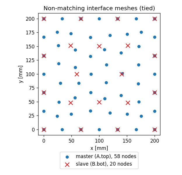
The four corners coincide (geometry forces them), but everywhere else the 20 coarse slave nodes fall between the 58 fine master nodes. There's no way to weld these by shared node id — which is exactly the situation a tie is for.
Master = fine, slave = coarse
The slave nodes get projected onto the master faces and
interpolated through that face's shape functions. Pick the finer mesh
as master (more faces to project onto, less interpolation error) and the
coarser as slave (fewer projections). We pass each side's interface
face explicitly via master_entities / slave_entities — a box Part has
six faces, and you only want to tie the one.
Step 2 — Declare the tie; the bridge emits it
g.constraints.tie(
    "blockA", "blockB",
    master_entities=[(2, t) for t in fA],
    slave_entities=[(2, t) for t in fB],
    dofs=[1, 2, 3], tolerance=1.0, stiffness=1.0e12, name="interface",
)
...
ops = apeSees(fem)
ops.element.FourNodeTetrahedron(pg="VolA", material=steel)
ops.element.FourNodeTetrahedron(pg="VolB", material=steel)
# (no tie code here — apeSees emits it for you)
This is the v2.0 headline. You declare the tie once, on the session,
naming the two parts and their interface faces. At get_fem_data it resolves
into one InterpolationRecord per projected slave node (the 20 above). Then
— and this is the part that used to be manual — apeSees(fem) emits those
records into the runnable model automatically, as ASDEmbeddedNodeElement
coupling elements, slotted in after the solid elements and before the loads.
There is no ops.equalDOF, no hand-written constraint, nothing about the tie
on the ops side. (Contrast the loads and supports, which you do re-declare
on ops; multi-point constraints are the thing the bridge carries over for
you.)
Two things worth knowing about the tie
ops.constraints.Transformation()— multi-point constraints need a constraint handler that can see them. The defaultPlainsilently ignores them; the bridge will auto-switch toTransformationwith a warning if you forget, but it's clearer to say it.- The penalty stiffness defaults to
"auto"— at emit the bridge sizes it from the host material (K = 10³·E_host·L_char), a few thousand times stiffer than the elements, which is all a penalty needs. Pass a number to override — but a number is unit-sensitive: the old fixed default (1e18) wrecked the conditioning of the solid's stiffness matrix in N/mm/MPa models and the solve failed to converge, which is why the default changed. Anything in the1e10–1e14band gives the same 0.128 mm answer here: the tie is effectively rigid; see below.
Step 3 — Read the load path and the displacement
spec.nodes(label="blockB.top", components=["displacement_z"], name="top")
spec.nodes(label="blockA.bot", components=["reaction_force_z"], name="base")
...
Rz = float(np.sum(r.nodes.get(label="blockA.bot", component="reaction_force_z").values[-1, :]))
Two reads tell the whole story. The base reaction is the equilibrium check that only the tie could pass: block B carries the load, block A is the only thing fixed, and the only connection between them is the tie. If the base reaction sums to the applied 1 MN — and it does, exactly — the tie carried every newton across the non-matching interface. The top displacement is the stiffness check: 0.128 mm against the bar's 0.125 mm.
The 2.7 % is the interface, and it's honest
A single fused mesh of this column gives exactly 0.125 mm. The tied model
gives 0.128 — about 3 % softer. Where does it come from? Not the penalty
stiffness: raise it from 1e12 to 1e14 and the answer doesn't budge, so the
tie is acting rigidly. It's the load transfer itself. Funnelling the
stress from a coarse mesh onto a fine one through shape-function interpolation
introduces a small, real interface compliance — a local softening right at
the join that a perfectly conformal mesh wouldn't have. Refine both sides
and it shrinks. It's the price of not matching the meshes, and 3 % is a fair
price for never having to.
So read the result as two facts: the tie transmits the load exactly (equilibrium is not negotiable), and it reproduces the monolithic stiffness to a few percent (the interpolation is good, not perfect). That's what a tie buys you.
What you just learned
- A tie joins non-matching meshes by projecting each slave node onto a
master face and binding it through that face's shape functions — the
general tool when nodes don't line up (
equal_dofis the special case when they do). - Declare it once on the session; the bridge emits it.
g.constraints.tie(...)resolves to interpolation records, andapeSees(fem)writes them into the runnable model as coupling elements — no tie code on the solver side. (Useops.constraints.Transformation()so the handler sees them.) - Keep the parts topologically distinct (a hair gap) so the geometry kernel doesn't fuse coincident faces into a conformal interface.
- The penalty stiffness defaults to
"auto"(sized from the host material at emit). If you pass a number instead, calibrate it — a value like the historical1e18default destroys the conditioning and the solve won't converge; ~1e12is right for N/mm/MPa. A record still carrying1e18(an oldmodel.h5) warns at emit. - The checks: the base reaction equals the applied load exactly (the tie carries it), and the column matches the monolithic bar to ~3 % (the inherent compliance of a non-matching interface, not a numerical error).
Where next
- Multi-part assembly — the no-contact version: stamped parts that don't touch, each addressed by label.
- Shell-on-solid (later) — a tie's mixed-dimension cousin: a 2-D shell wall tied onto a 3-D solid footing, with per-node DOF bookkeeping.
- Tie non-matching meshes — the how-to recipe for
the tie options (
tolerance,stiffness, master/slave choice) on their own.